


The article is protected by copyright. Publishing the entire article or its parts without a clear reference to the source (a link to the Könner & Söhnen website) is not permitted.
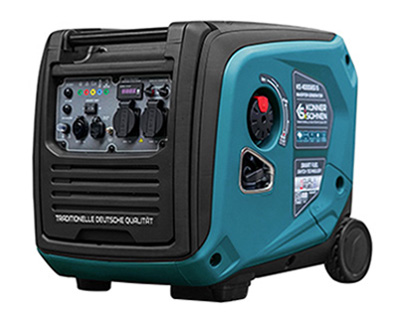
Backup power solutions with inverter generator KS 4000iES ATS Version 2
With the KS 4000iES ATS Version 2, an automatic emergency power supply can be implemented without the generator having to be permanently installed.
The KS 4000iES ATS inverter generator is equipped with the ATS module, which enables a lot of innovative emergency power solutions. The generator delivers a “clean” sine wave voltage 230V 50 Hz with an output of up to 3.5 kW, which is usually enough for the bare essentials.
Internal circuit diagram of the inverter generator KS 4000iES ATS version 2
You can manually switch the generator on (RUN position) or off (OFF position) using the multi-function rotary switch on the side (petrol tap, ignition, control power supply). Use the red button on the multifunction switch to start the generator in manual mode.
With the ATS SWITCH you switch the automatic mode on (ATS SWITCH to ON) or off (ATS SWITCH to OFF).
The generator's ATS module monitors the 230V voltage at the MAINS INPUT in automatic mode, starts the generator as soon as it fails and stops within approx. 1 minute as soon as the 230V at the MAINS INPUT is back.
The left Schuko socket is connected to the output of the inverter module and is only active when the generator is running. From this socket you can realize an automatic emergency power supply for a house, an office, or a group of electricity consumers. In addition, an external automatic transfer switch is required, which is available commercially in different versions.
The right Schuko socket is switched from the MAINS INPUT to the inverter module with a relay and is to be used for emergency power solutions where only 1 power consumer is to be supplied by the generator. No additional switch is required.
The two Schuko sockets are active as soon as the generator is running and producing voltage. When using the generator mobile, it is irrelevant which socket you use. The entire power of the generator can be taken from either one or two sockets.
The internal power supply supplies the ATS module and, if necessary, charges the lithium battery installed in the generator, so that the generator always remains ready for operation in standby mode (230V applied to the MAINS INPUT). The battery supplies the ATS module in the event of a power failure until the generator has started. As soon as the generator generates its own 230V voltage, the power supply unit works again, supplies the ATS module and charges the battery. Internal power supply also works when the generator is switched off (rotary switch to OFF) if the 230V is present at the MAINS INPUT. This way you can recharge the battery every now and then, even when the generator is not in use. If the battery is to be discharged through several starting attempts, there is always the option of starting the generator manually.
The inverter module has built-in electronic overload and short-circuit protection and the circuit breaker at the generator output only serves as an additional protection.
Automatic emergency power supply to a house, an office or a group of electricity consumers from the left socket of the KS 4000iES ATS version 2 generator
Recommended connection diagram:
The generator is connected to the N side of the automatic transfer switch, which has a switching priority, so that when the main power returns, the switch does not immediately switch to the utility grid, but only when the generator turns off its output. The KS 4000iES ATS version 2 generator analyzes the voltage at its MAINS INPUT for approx. 1 minute and only then switches off the left socket, thus enabling switching to the main power supply. This corresponds to the regulation according to which an automatic switching device may not switch to the public power grid immediately, but with a delay.
Even if the generator is only connected in the event of a power failure, we recommend using the automatic mode so that you don't have to keep checking whether the main power supply is back on, but rather the generator notices it itself and its left Schuko socket after about 1 minute switches off, which allows the automatic transfer switch (not included) in the distribution box to switch to the main power supply. The right Schuko socket will be switched from the inverter module to MAINS INPUT.
The KS 4000iES ATS Version 2 is built as a portable power source as an IT system. The neutral conductor is not bonded to frame. A TN system with the grounded neutral conductor is required for a home feed-in. To do this, the neutral conductor from the generator must be connected to house earthing bar (PE) at the connection point (on the circuit diagram behind the feed inlet).
The cable to the building is considered the generator output cable and the TN system is only created when the generator is connected to the house. N and PE conductors run separately from the automatic transfer switch.
Automatic emergency power supply from a one power consumer from the right socket of the generator KS 4000iES ATS Version 2
This simpler solution is intended for a power consumer that can be supplied in both the TT and IT systems.
Recommended connection diagram:
When operating from the main power source, the right Schuko socket provides the same system (IT, TT) as on the MAINS INPUT. After switching the power supply to the generator, the right Schuko socket only supplies the IT system without the grounded neutral conductor. Please note that only 1 electricity consumer may be supplied in this way without additional protective measures.
If the generator has to be uninstalled for any reason, it is sufficient to connect the Schuko socket (on the house wall in the picture) to the power inlet so that the load to be supplied from the main power source.
Electricity consumers such as heating are generally not allowed to be operated in the IT system. How to supply your heating (except heat pumps or electric boilers) with the KS 4000iES ATS Version 2 can be found in our separate article on this topic on our website.
The cable from the generator to the power socket is not included. It is a standard extension with a Schuko plug 230V 16A at one end and a CEE 230V 16A socket at the other end, which is commercially available in different lengths.
The generator monitors the voltage in the Schuko socket, which is connected in front of the automatic transfer switch and protected by a MCB and a RCD or by RCBO (MCB and RCD in one). This socket without the generator connected can be used as a normal outdoor socket. This socket no longer has any voltage in the event of a power outage and this is crucial for the ATS control module of the generator. It is a signal to start the generator. The Schuko plug can be reversed without having any effect on the entire system.
A connector for the MAINS INPUT is supplied with the generator. The cable to the Schuko plug must be built separately. You buy a cable with a Schuko plug in the desired length and install the supplied plug on its free end.
The generator on the circuit diagram is not permanently installed, but rather connected to the pre-installed Schuko socket and the CEE 230V 16A wall inlet as required. This means that the generator can also be used mobile if necessary. A permanent installation is of course also possible, but you need a suitable room with sufficient ventilation and an exhaust system. Additional forced ventilation can be connected to the N side of the automatic transfer switch switch and runs only while the generator is running and producing voltage.
If you have further questions, please contact our technical support at:
Disclaimer:
These instructions can only be taken as a recommendation, are illustrative and must be adapted to the exact local circumstances and conditions during installation. The installation itself should be carried out in compliance with all standards and regulations. We take no responsibility for the wrong installations and their consequences.