


Generator for heating has become indispensable in modern heating systems. Even if carbon is used as the energy carrier, electricity is needed for the controls, circulating pumps, etc. and it is extremely important to design the backup power for heating system correctly.
Such power consumers as e.g. the gas boiler cannot simply be supplied from the socket of the generator because the heating requires a TN system with the earthed neutral conductor.
The heating must be supplied either as part of a complete house feed-in or by a switching device specially built for the heating.
You can find out how to supply your heating from an emergency generator as part of a home feed-in in our information material on our website.
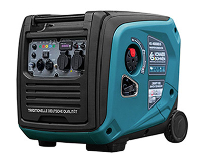
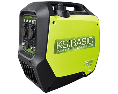
Here we inform you about an automatic backup power supply for your heating based on the inverter generator KS 4000iES ATS Version 2.
Modern heating systems usually have electronic control modules, which usually need a "clean" inverter sinusoidal voltage and the KS 4000iES ATS delivers this with an output power of up to 3.5 kW, which is sufficient for most heating systems. Exceptions are heating systems that require 3-phase 400V three-phase current. The KS 4000iES ATS only supplies 230V.
The KS 4000iES ATS has an internally installed ATS module that can monitor a main power source. This allows the generator to be used without an external ATS unit.
KS 4000iE S ATS Version 2 inside
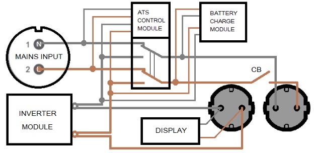
The right 230V socket is active both when operating from the MAINS INPUT and when operating from the generator.
The socket on the left is connected to the output of the inverter module and is only active while the generator is running. The inverter module has built-in electronic overload and short-circuit protection.
In this way, the KS 4000iES ATS Version 2 can monitor the main power source and start when required. This means that different emergency power supply systems can be implemented, including heating system.
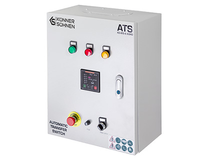
In addition, an automatic transfer switch is required, which can be installed in the distribution board or next to the device to be powered, and switches only based on the voltage present on its sides.
Connecting the KS 4000iES ATS Version 2 generator to the heating system
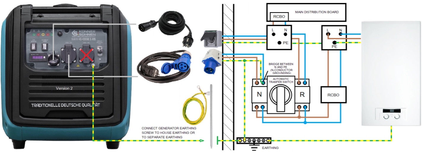
The generator is connected to the N-side of the automatic transfer switch, which has priority switching, so when the main power returns, the switch does not switch to the utility grid immediately, but only when the generator shuts off its output. The KS 4000iES ATS version 2 generator analyzes the voltage at its MAINS INPUT connection for about 1 minute and only then does the left socket switch off and thus enable switching to the main power supply. This corresponds to the regulation according to which an automatic switching device must not switch over to the public power grid immediately, but with a delay of 1 minute.
The neutral conductor of the generator is first grounded in the house by installing a bridge between N and PE on the transfer switch. The transfer switch switches the electricity consumers entitled to backup power from one TN system to the other.
The generator monitors the voltage in the socket, which is connected in front of the switch and protected by a circuit breaker and an RCD or by RCBO (overload and leakage protection in one). This socket without the connected generator can be used as a normal outdoor socket. This outlet is de-energized during a power outage and this is critical to ATS control of the generator. It is a signal to start the generator.
The generator on the circuit diagram is not permanently installed, but connected to the pre-installed Schuko socket and the CEE 230V 16A inlet as required. This means that the generator can also be used elsewhere if required.
The Schuko plug of the two connection cables can be reversed without anything happening. In the scheme, this has no effect on N and L behind the CEE feed socket (CEE 230V 16A wall inlet), because the neutral conductor is only grounded behind the CEE 230V inlet.
Only the MAIN INPUT plug is supplied with the generator. The cable to the Schuko plug is made of the appropriate length by the electrician who does the installation. The cable Schuko plug to CEE 230V 16A coupling is commercially available in different lengths.
If you have further questions, please contact our technical support at:
Disclaimer:
These instructions can only be taken as a recommendation, are illustrative and must be adapted to the exact local circumstances and conditions during installation. The installation itself should be carried out in compliance with all standards and regulations. We take no responsibility for the wrong installations and their consequences.